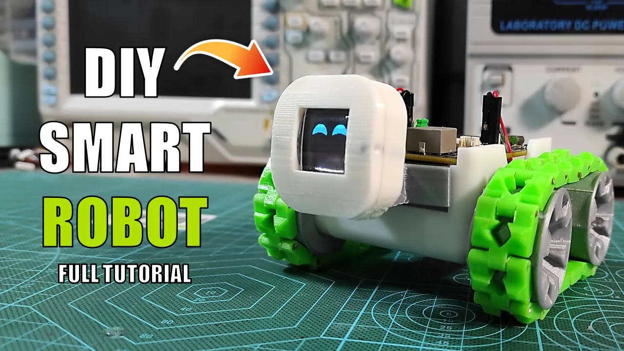
Welcome to the second version of the DIY SMARS Robot! In this video, I'll show you how to produce this enhanced robot with features like OLED display, RGB LEDs, and a buzzer for melodies. Follow along as I walk you through the circuit design in Altium Designer, assembly with a PCB stencil, and 3D printing the mechanical parts. Watch as the robot comes to life with motion control, Bluetooth connectivity, and customizable eye expressions. Don't miss out on this exciting upgrade to the SMARS Robot!
Useful Links:
1. Octopart (to source electronics components): https://octopart.com/
2. JLCPCB (to order PCBs): https://jlcpcb.com/?from=TIP
3. Check out the FREE Altium 365 potential and advantages: https://www.altium365.com/yt/diyguychris
👉 STL Files credits: https://www.thingiverse.com/thing:2662828/files
👉 Old SMARS Version: https://www.youtube.com/watch?v=tTVDAPJWG2k&t=320s
👉Bluetooth configuration: https://youtu.be/A0uFtI_hX6Q?si=wJPGf7btzNBEmGTt
👉 Download Arduino code: https://www.mediafire.com/file/0c1jkdpkmdgtgtc/SMART_Robot_V1.rar/file
👉 Download Android App: https://www.mediafire.com/file/xwjssd96jc8uwd5/App.rar/file
Chapter Titles:
0:01 Introduction: DIY SMARS Robot
0:24 Comparison, old and new versions
01:11 Circuit schematic design
02:26 PCB Design and Manufacturing Process
03:48 Circuit board Assembly
05:35 Robot mechanical parts assembly
07:19 Android App and Arduino code
08:23 Final test
Needed Parts :
➡️ Electronics Components:
⚡Atmega328p Microcontroller (SMD VQFN version)
⚡L293 Motor Driver (SMD)
⚡CH340 IC (USB to TTL converter)
💡WS2812 RGB LEDs (12 pieces)
🔉Active Buzzer
⚛SIL Headers (for ultrasonic sensor and OLED display)
🔋9V Battery
⚡LM317 Voltage Regulator
⚡Resistors and Capacitors
⚡Diodes and Transistors
⚡Crystal Oscillator (16MHz)
➡️ PCB and Soldering:
💠Custom PCB (ordered from JLCPCB)
💧Solder Paste
⚙️PCB Stencil
💧Flux Remover Solvent
🔥Hot Plate (or reflow oven)
➡️ Mechanical Parts:
🛠️3D Printed Parts (STL files available on Thingiverse)
🛢️1.6mm Brass Wire (or 1.75mm 3D printer filament for chain joints)
⚙️Small DC Motors (2 pieces)
🔩Screws and Nuts (for assembly)
🗞️Super Glue
➡️ Displays and Sensors:
🖥️OLED Display
📡Ultrasonic Sensor (HC-SR04 or similar)
ᛒ HC-05 Bluetooth Module
➡️ Tools and Software:
🔬3D Printer
💿Altium Designer (for circuit design)
💿Arduino IDE
💿MIT App Inventor
🖋️Soldering Iron and Solder
🔎Microscope (for inspecting solder joints)
🔌USB-C Cable (for programming)
➡️ Additional Components:
🔗Threaded Inserts (2mm for OLED display housing)
★☆★ 💻 FOLLOW ME BELOW 💻 ★☆★
Instructables: http://www.instructables.com/member/M...
Hackaday : https://hackaday.io/MegaDAS
Facebook : https://www.facebook.com/MEG.DAS1/?fr...
Twitter : https://twitter.com/MEGADAS1
Hackster : https://www.hackster.io/mega-das
Keywords
#diy #arduino #robot #maker #circuit #android #iot #bluetooth #creative #ideas #SMARSRobot #PCBDesign #3dprinting
arduino,robot,diy,maker,circuit board,smars,smart robot,smart arduino robot,arduino robotics,easy diy project,homemade robot,creative idea,2024 best arduino project,arduino projects
